Part of an Eight-Volume Set
This is the third of eight detailed volume pages expanding on [[planetary-stewardship-transducer]] (AW-04). PST-103 builds directly on the mechanical support structures and service access established in [[pst-101-mechanical-systems]] (AW-10) and the pump power, valve actuation, and instrumentation established in [[pst-102-electrical-systems]] (AW-11). PST-103 defines the fluid pathways that connect these disciplines into one operational platform.
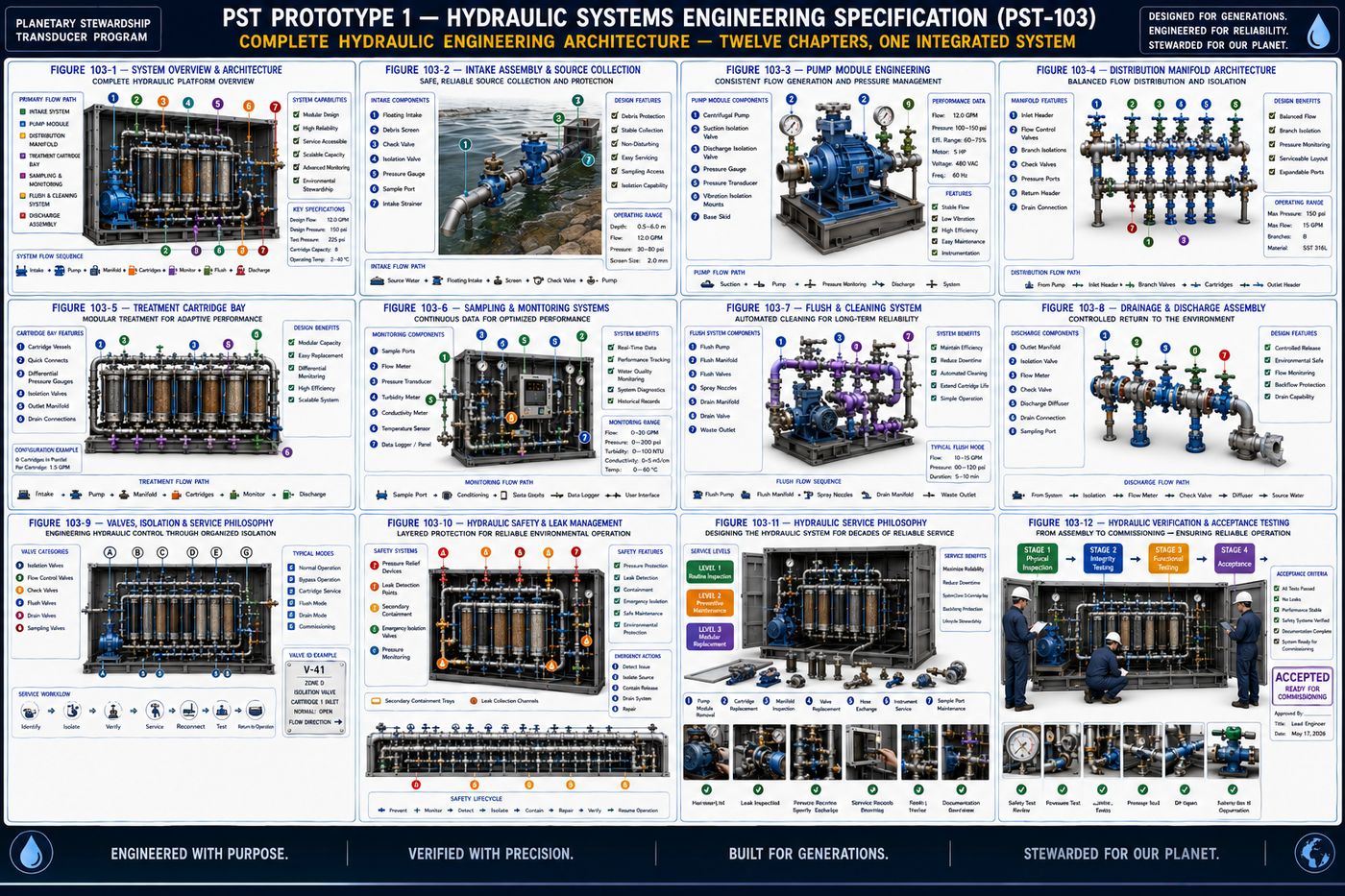
PST-103 defines the complete hydraulic architecture of Prototype 1: the design philosophy governing every valve and pipe, the overall hydraulic pathway from source water to controlled discharge, the intake and source water system, the pump module that serves as the platform's hydraulic heart, the manifold and distribution network, the standardized treatment cartridge hydraulic interface, the sampling and monitoring system that turns operation into measurement, the flush and drainage system, the valve and isolation philosophy, hydraulic safety and leak management, the service philosophy governing hydraulic maintenance, and the verification and acceptance program required before the hydraulic system enters service.
All twelve chapters are covered in full below, following the specification's own structure: purpose, engineering intent, philosophy, architecture, and a chapter summary.
I. Hydraulic Design Philosophy
PST-103 builds directly on the mechanical structure established in PST-101 and the electrical power and control established in PST-102, defining how water moves through that established architecture. Seven guiding principles govern the hydraulic design: controlled flow, modularity, serviceability, measurement, adaptability, containment, and documentation, the same disciplined framework that organized the mechanical and electrical volumes, now applied to the platform's circulatory system.
II. Overall Hydraulic Architecture
Rather than examining individual hydraulic components in isolation, the platform is first viewed as an integrated fluid system in which water moves through organized stages from environmental intake to controlled discharge, defining the complete pathway every subsystem supports. Water follows a predictable sequence: source water, the intake assembly, the primary pump module, the main distribution manifold, the treatment cartridge bay, sampling and instrumentation, the discharge assembly, and finally environmental return or collection, with every stage measurable, serviceable, and independently maintainable.
2.1 The Seven Hydraulic Zones
| Zone | Function |
|---|---|
| A — Source Intake | Water collection, debris exclusion, initial screening, source isolation, and intake monitoring; the entry point of the hydraulic system |
| B — Pump Module | Water movement, pressure generation, controlled flow, and hydraulic stabilization; the hydraulic heart of the platform |
| C — Distribution Manifold | Directing flow, isolating treatment branches, pressure balancing, and expansion connections; every downstream pathway originates here |
| D — Treatment Cartridge Bay | Interchangeable modules, sediment filtration, activated carbon or biochar, mineral conditioning, biological media, and experimental hydraulic modules, intentionally modular so treatment technologies can evolve without redesigning the backbone |
| E — Sampling & Monitoring | Continuous measurement before, during, and after treatment via flow meters, pressure transducers, and water quality probes, allowing representative collection at multiple process stages |
| F — Flush & Cleaning | Cartridge flushing, line cleaning, bypass operation, controlled drainage, and maintenance isolation, supporting long-term hydraulic reliability |
| G — Discharge Assembly | Returns processed water to the source environment, a storage vessel, an irrigation system, or a research collection tank, with discharge conditions kept measurable and documented |
Water is expected to follow a controlled engineering sequence: collect, protect, move, treat, measure, compare, document, and return, ensuring hydraulic performance is supported by measurable engineering data rather than assumption. Prototype 1 supports multiple hydraulic pathways operating simultaneously where appropriate, a primary treatment flow through the treatment modules, a bypass flow for maintenance or comparison testing, a sample flow that minimizes disturbance to the primary stream, and a flush flow for cleaning, each independently controllable through dedicated valves. Hydraulic functions remain physically organized, intake piping, pressure piping, sampling tubing, flush circuits, and drainage piping kept separate to simplify maintenance and reduce cross-contamination risk, and the architecture reserves standardized interfaces for future treatment cartridges, research modules, and increased pumping capacity through defined connection points rather than redesign.
III. Intake and Source Water System Engineering
The Intake and Source Water System provides the controlled hydraulic interface between the platform and the surrounding water source, safely collecting environmental water, excluding large debris, protecting downstream equipment, and establishing a repeatable hydraulic starting point for every treatment cycle. Prototype 1 is intended to operate with a wide range of source waters, natural surface waters (rivers, streams, lakes, wetlands), agricultural systems (irrigation canals, farm ponds, drainage channels), research applications (laboratory reservoirs, controlled test basins), and industrial or municipal applications (process water, stormwater retention, reclaimed water research), with the intake architecture remaining fundamentally unchanged while accessories adapt to the application.
The Intake Assembly, the first hydraulic module in the platform, comprises an intake head, coarse debris screen, protective strainer, isolation valve, flexible suction connection, service union, and intake pressure port, designed for rapid removal and inspection. Debris exclusion targets leaves, twigs, stones, aquatic vegetation, and floating debris while protecting wildlife where practical, balancing equipment protection against hydraulic performance, and before water reaches the Pump Module, the assembly establishes stable flow conditions, reduced turbulence, uniform inlet velocity, and minimized air entrainment, which improve both pump efficiency and measurement accuracy. The intake incorporates hydraulic isolation, a main intake valve, quick-disconnect unions, and a drain connection, so it is serviceable without disturbing downstream modules, and representative instrumentation, intake pressure, source temperature, source conductivity, and flow indication, provides baseline hydraulic data before treatment begins. The intake is also designed to minimize environmental disturbance, low intake velocity, minimal sediment disruption, and controlled return flows, with environmental stewardship beginning at this first hydraulic gateway.
IV. Pump Module Engineering — The Hydraulic Heart
The Pump Module provides the controlled hydraulic energy required to move water throughout the platform, establishing stable flow, maintaining predictable operating pressures, and providing reliable performance across a wide range of environmental conditions. Prototype 1 treats the pump as the hydraulic heart of the platform: rather than designing the surrounding architecture around one specific pump model, the platform is designed around standardized mounting, plumbing interfaces, and service geometry, allowing future pump technologies to be integrated while preserving the rest of the hydraulic system.
The complete assembly, pump, mounting base, suction and discharge connections, isolation valves, flexible couplings, vibration isolators, and pressure and flow instrumentation, is removable as a single module. Hydraulic stability is prioritized over maximum flow capacity: the suction side promotes adequate net positive suction head, minimal flow restriction, and reduced turbulence, while the discharge side includes a check valve, pressure transducer, isolation valve, and pressure relief provisions supporting both normal operation and maintenance isolation. Vibration is controlled through elastomeric isolation mounts, flexible hose sections, and balanced mounting geometry, protecting the hydraulic system and improving measurement quality, and representative instrumentation, suction and discharge pressure, differential pressure, flow rate, and pump and motor temperature, provides continuous evaluation of performance. Since the Pump Module is expected to be one of the most frequently serviced hydraulic assemblies, complete module replacement is designed to be possible without disturbing downstream assemblies, and the surrounding hydraulic architecture is engineered to remain stable while individual pump technologies, variable-speed operation, higher-capacity pumps, or specialized impeller designs, continue to improve.
V. Manifold and Distribution Network Engineering
The Manifold and Distribution Network receives pressurized flow from the Pump Module and distributes water through organized hydraulic pathways serving treatment cartridges, sampling systems, bypass circuits, and maintenance loops, ensuring every downstream subsystem receives predictable flow under controlled conditions. Prototype 1 uses a centralized hydraulic manifold: rather than routing individual piping directly from the pump to each treatment assembly, flow first enters a common manifold where it can be directed through dedicated branches, improving flexibility and simplifying maintenance.
5.1 Five Hydraulic Branches
| Branch | Function |
|---|---|
| A — Primary Treatment | Directs flow through the primary treatment cartridge sequence |
| B — Sampling Circuit | Provides controlled flow to sampling stations while minimizing disturbance to the primary stream |
| C — Bypass Circuit | Allows untreated or comparison flow to bypass selected treatment modules during maintenance or experimentation |
| D — Flush Circuit | Supplies water for cartridge flushing, line cleaning, and maintenance operations |
| E — Expansion Ports | Reserved hydraulic interfaces for future treatment technologies or research modules |
Each branch is independently controllable through dedicated isolation valves, and stable pressure distribution, uniform branch pressure, controlled pressure losses, and balanced manifold geometry, ensures downstream modules operate within their intended design envelope. Where multiple branches operate simultaneously, manual balancing valves and adjustable flow restrictors provide repeatable operating conditions, and representative instrumentation, inlet and outlet pressure, branch flow measurement, and differential pressure, gives continuous visibility into distribution performance. Every major branch is independently isolated through ball or butterfly valves, quick-disconnect unions, and drain valves, permitting maintenance without disrupting unrelated pathways, and the manifold remains accessible from the front service area established in PST-101. The architecture reserves capacity for additional treatment branches and parallel hydraulic circuits, and is expected to remain in service through multiple generations of treatment technology: the manifold is intended to outlive many of the technologies connected to it.
VI. Treatment Cartridge Hydraulic Architecture
This chapter establishes the standardized hydraulic interface through which interchangeable treatment technologies, filtration, adsorption, mineral conditioning, biological media, and future concepts not yet developed, are integrated into the platform. Prototype 1 separates the hydraulic platform from the treatment technology itself: the machine does not depend on one filter, it depends on a standardized cartridge interface, so the platform remains unchanged while cartridges evolve.
The Treatment Bay consists of a structural cartridge frame, hydraulic inlet and outlet manifolds, cartridge mounting rails, isolation valves, pressure measurement ports, differential pressure instrumentation, and quick-disconnect fittings, with each cartridge occupying an independent hydraulic position. Every cartridge provides guided installation, positive positioning, hydraulic alignment, mechanical retention, and an identification plate, and connects through identical hydraulic geometry, inlet, outlet, pressure ports, vent, and drain connections, regardless of cartridge contents. Each cartridge is individually isolated through inlet and outlet isolation valves and bypass capability, so a single cartridge can be serviced while the remainder of the system continues operating where practical, and differential pressure is measured across each cartridge as a primary indicator of filter loading, flow restriction, fouling, and maintenance timing. Routine maintenance emphasizes complete cartridge exchange rather than field disassembly, and the platform is engineered so that cartridge geometry, hydraulic interfaces, and service procedures all remain fixed while innovation occurs within the cartridge rather than the machine: the platform is designed to outlive the treatment technology.
VII. Sampling and Monitoring System Engineering
The Sampling and Monitoring System provides the hydraulic infrastructure necessary to observe, measure, document, and verify platform performance, transforming hydraulic operation from a process of observation into one of measurable engineering verification. Prototype 1 establishes monitoring locations throughout the hydraulic pathway rather than only at the inlet and outlet, source intake, pump suction and discharge, manifold inlet, individual treatment cartridges, cartridge outlet, final discharge, and the flush circuit, allowing engineers to isolate hydraulic changes as they occur rather than relying solely on overall system performance.
Dedicated sampling stations provide representative collection at five critical locations: source water for baseline environmental conditions, pre-treatment water immediately downstream of the pump, intermediate process sampling between treatment stages, post-treatment water after the full sequence, and final discharge water immediately prior to environmental return. Representative instrumentation includes flow meters, pressure transducers, differential pressure sensors, temperature sensors, conductivity probes, and optional pH, dissolved oxygen, turbidity, and oxidation-reduction potential probes, all modular and independently replaceable, and sampling ports are designed for controlled flow, representative collection, and minimal dead volume without interrupting normal operation. Monitoring data supports hydraulic diagnostics, trend analysis, maintenance scheduling, and treatment comparison, timestamped and associated with the corresponding operating configuration, and instrumentation accuracy depends on periodic calibration standardized across all Prototype 1 platforms. The monitoring infrastructure is designed to support rapid identification of hydraulic abnormalities, pressure loss, flow reduction, cartridge loading, air entrainment, and pump degradation, helping identify root causes before significant performance degradation occurs.
VIII. Flush, Cleaning, and Drainage System Engineering
This system provides the hydraulic infrastructure necessary to clean, purge, isolate, drain, and prepare the platform for routine maintenance, cartridge replacement, seasonal shutdown, and recommissioning, with cleaning capability built in as a permanent engineering feature rather than an afterthought. Prototype 1 separates operational flow from maintenance flow entirely: normal treatment water never depends on maintenance plumbing, and dedicated cleaning circuits provide controlled pathways for flushing, draining, and servicing without altering the primary treatment architecture.
The Flush Circuit, a flush supply connection, isolation valves, a dedicated flush manifold, and cartridge flush ports, is physically integrated but hydraulically independent from the primary treatment pathway, supporting four maintenance modes: cartridge flush, removing accumulated debris from treatment cartridges; line flush, cleaning supply piping and manifolds; drain and service, safely depressurizing and draining selected sections before maintenance; and seasonal preservation, removing standing water for extended shutdown. Each mode follows a documented valve sequence for safe, repeatable operation. Dedicated drainage pathways, cartridge drains, manifold drains, pump drain, and low-point drains, direct fluids to approved collection or disposal locations appropriate for the deployment environment, and contamination control, dedicated flush pathways, controlled drain routing, and cartridge isolation before removal, protects both measurement quality and treatment performance. Instrumentation during maintenance, flush pressure and flow, drain verification, and pressure equalization, assists technicians in confirming successful operations, and the platform is engineered so cleaning procedures, drainage pathways, and maintenance interfaces all remain standardized and accessible, with preventive maintenance designed into the platform from the beginning rather than added afterward.
IX. Valves, Isolation, and Service Philosophy
This chapter establishes the engineering principles governing hydraulic flow control, equipment isolation, maintenance access, and service safety throughout the platform. Every valve serves a defined engineering purpose beyond simply opening or closing flow, and together the valve network creates a controllable hydraulic architecture supporting routine operation, diagnostics, maintenance, and future expansion without unnecessary disruption to adjacent systems. Prototype 1 treats valves as engineered control points rather than plumbing accessories, with valve placement determined by serviceability as much as hydraulic performance.
Representative valve categories include isolation valves that separate hydraulic sections during maintenance, flow control valves that adjust operating flow, check valves that prevent reverse flow, drain valves for controlled depressurization, flush valves that direct maintenance flow, sampling valves for representative collection without interrupting operation, and expansion isolation valves reserving future interfaces. Every major hydraulic assembly, the intake, pump module, distribution manifold, individual treatment cartridges, sampling network, flush system, and discharge assembly, is independently isolated, and the hydraulic architecture divides into seven independently serviceable zones matching those same assemblies, each isolable through documented valve sequences. The valve network supports six operational modes: normal treatment, bypass operation, cartridge service, flush mode, drain mode, and commissioning mode, each following documented valve-position procedures, and every valve receives permanent identification, valve number, hydraulic zone, function, and normal operating position, corresponding directly with engineering documentation. Valve placement prioritizes technician usability, comfortable operating height, clear labeling, and visible flow direction, and future hydraulic modules are expected to integrate using the same valve philosophy established by Prototype 1, preserving consistency across future generations.
X. Hydraulic Safety and Leak Management
This system establishes the engineering principles, protective features, and operational practices required to minimize hydraulic hazards, detect abnormal conditions, contain unintended fluid releases, and protect personnel, equipment, and the environment, with safety integrated into the platform architecture from the beginning rather than added after construction. Prototype 1 follows a layered safety philosophy: protection is provided through multiple independent measures, robust component selection, controlled operating pressures, leak detection, pressure monitoring, hydraulic isolation, secondary containment, and emergency shutdown capability, rather than relying on any single safeguard.
The hydraulic system operates within defined design limits through pressure relief valves, pressure transducers, high-pressure alarms, and controlled startup sequences, and the platform incorporates multiple leak detection methods, visual inspection points, drip trays, leak collection channels, and pressure-loss monitoring, to identify abnormal conditions before they become significant failures. Potential leak locations incorporate engineered secondary containment, pump drip trays, cartridge containment basins, drain collection channels, and service catch basins, minimizing environmental release and simplifying cleanup, and the architecture provides rapid emergency isolation, intake isolation, pump shutdown, branch isolation, and cartridge isolation, with procedures documented and readily accessible. Environmental stewardship extends to controlled discharge, managed drainage, spill containment, and responsible disposal of spent treatment media, and routine safety inspections cover leak inspection, valve verification, relief device inspection, and containment inspection to support proactive maintenance. Safety is maintained throughout the platform's complete operational life through periodic inspection, documented maintenance, and continuous monitoring, evolving alongside the platform while preserving consistent engineering principles.
XI. Hydraulic Service Philosophy
Hydraulic maintenance is organized into four progressive service levels, mirroring the philosophy established in PST-101 and PST-102 but focused specifically on hydraulic systems.
| Level | Representative Activities |
|---|---|
| 1 — Routine Inspection | Visual leak inspection, pressure gauge review, flow verification, valve position confirmation, hose inspection; no disassembly required |
| 2 — Preventive Maintenance | Cartridge replacement, seal and O-ring inspection and replacement, valve lubrication, pump inspection, instrument calibration verification, on scheduled intervals |
| 3 — Modular Replacement | Complete assemblies replaced rather than rebuilt in the field: intake assembly, pump module, distribution manifold, treatment cartridge assemblies, sampling stations, with removed modules refurbished under controlled workshop conditions |
| 4 — Major Hydraulic Refurbishment | At extended intervals: complete manifold replacement, pump modernization, hydraulic piping replacement, instrumentation upgrades; the hydraulic architecture remains while technologies evolve |
Routine maintenance, cartridge exchange, valve inspection, pressure verification, and instrument replacement, is designed to be performed from designated service access areas, with major structural disassembly rarely required. Every activity produces a permanent engineering record, date, technician, hydraulic assembly serviced, observed condition, and verification results, and diagnostics, pressure and flow trend analysis, differential pressure monitoring, and leak investigation, are expected to identify root causes before corrective action begins. Prototype 1 encourages standardized spare hydraulic assemblies, treatment cartridges, pump assemblies, valve assemblies, and sensor hardware, reducing downtime and simplifying logistics, and hydraulic systems are evaluated continuously throughout their operational life, inspection frequency, service history, performance trends, and component aging, minimizing unexpected failures while encouraging continuous improvement. Together with the mechanical and electrical service philosophies established in PST-101 and PST-102, this chapter establishes a unified maintenance philosophy across all three major engineering disciplines, intended to remain consistent throughout future PST generations.
XII. Hydraulic Verification and Acceptance Testing
This program confirms that the hydraulic systems have been installed, documented, tested, and demonstrated in accordance with the engineering design intent. Verification confirms the hydraulic architecture has been assembled correctly; acceptance confirms it is ready for integrated commissioning. Verification progresses through four stages: physical inspection, confirming equipment installation against approved documentation; hydraulic integrity testing, verifying integrity before routine operation; functional testing, demonstrating correct operation of every subsystem under representative conditions; and acceptance, confirming the complete architecture satisfies engineering requirements.
Physical inspection covers pipe routing verification, valve identification, hose and fitting inspection, instrument installation, and cartridge installation. Hydraulic integrity testing covers hydrostatic pressure testing, leak inspection, isolation verification, valve operation, and pressure retention testing, confirmed before full operational testing. Functional testing demonstrates stable source collection and debris screening at the intake; flow generation, pressure stability, and vibration assessment at the Pump Module; branch operation and flow balancing at the Distribution Manifold; cartridge installation and differential pressure monitoring at the Treatment Cartridge Bay; sample collection and instrument operation for Sampling and Monitoring; flush and drain operation for the Flush and Cleaning System; and controlled discharge and flow verification at the Discharge Assembly, with every subsystem expected to demonstrate stable, repeatable performance. Safety verification covers pressure relief operation, emergency isolation, leak detection, and secondary containment inspection, completed before operational acceptance, and a documentation audit reviews hydraulic schematics, pipe schedules, valve schedules, and instrument schedules for consistency. Every verification event produces a permanent engineering record, and successful hydraulic verification authorizes progression to integrated platform commissioning across the mechanical, electrical, control, and treatment systems, with representative verification activities repeated following any significant hydraulic modification.
Protected — Detailed Engineering Package
Exact pipe sizes and materials, pump performance curves and NPSH calculations, valve schedules and part numbers, flow and pressure design setpoints, hydrostatic test pressures, and the bill of materials for every assembly described above are held under NDA pending requirements freeze and physics validation, consistent with the source specification's own stated pre-construction status.
Full Specification Available Under Signed NDA ↗Documentation Summary
The seven-zone hydraulic architecture, the intake and source water system, the pump module engineering, the manifold and distribution network, the standardized treatment cartridge hydraulic interface, the sampling and monitoring architecture, the flush and drainage system, the valve and isolation philosophy, and the hydraulic safety and leak management framework are original work product of Joshua Farrior, developed under CHRISTOS™ Energy, Technology & Harmonic Design Consulting, LLC.
Held under NDA pending further development: pipe sizing and material calculations; pump performance curves and NPSH analysis; valve schedules and component part numbers; design flow rates, pressure setpoints, and hydrostatic test pressures; the complete engineering drawing package; the bill of materials; and fabrication and acceptance test procedures beyond the verification stages described above.
© 2026 Joshua Farrior · Christos™ Energy, Technology & Harmonic Design Consulting, LLC · All Rights Reserved · Business ID: 202511071941923 · Christos™ trademark registered on the USPTO Principal Register · christosenergy.com