Part of an Eight-Volume Set
This is the first of eight detailed volume pages expanding on [[planetary-stewardship-transducer]] (AW-04), the introduction to the Planetary Stewardship Transducer program. AW-04 covers the program's mission, nine-system architecture, and twelve-assembly configuration at overview depth; this page goes chapter by chapter through PST-101, the Mechanical Systems Engineering Specification, at full detail. Consistent with the source specification's own stated status, this volume is architecturally complete: every mechanical chapter, philosophy, and verification process is defined, but detailed calculations, component sizing, and fabrication drawings are still to follow.
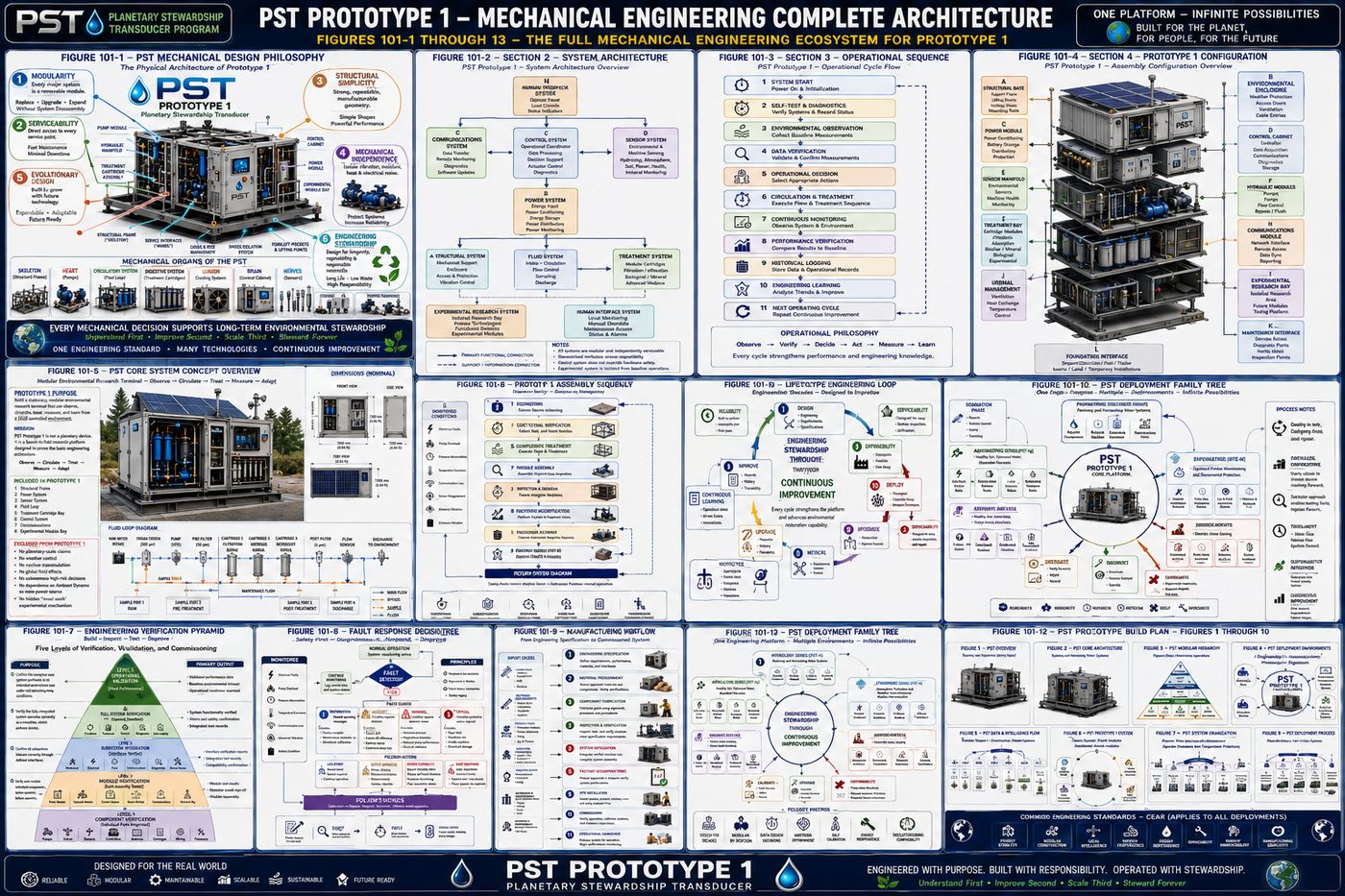
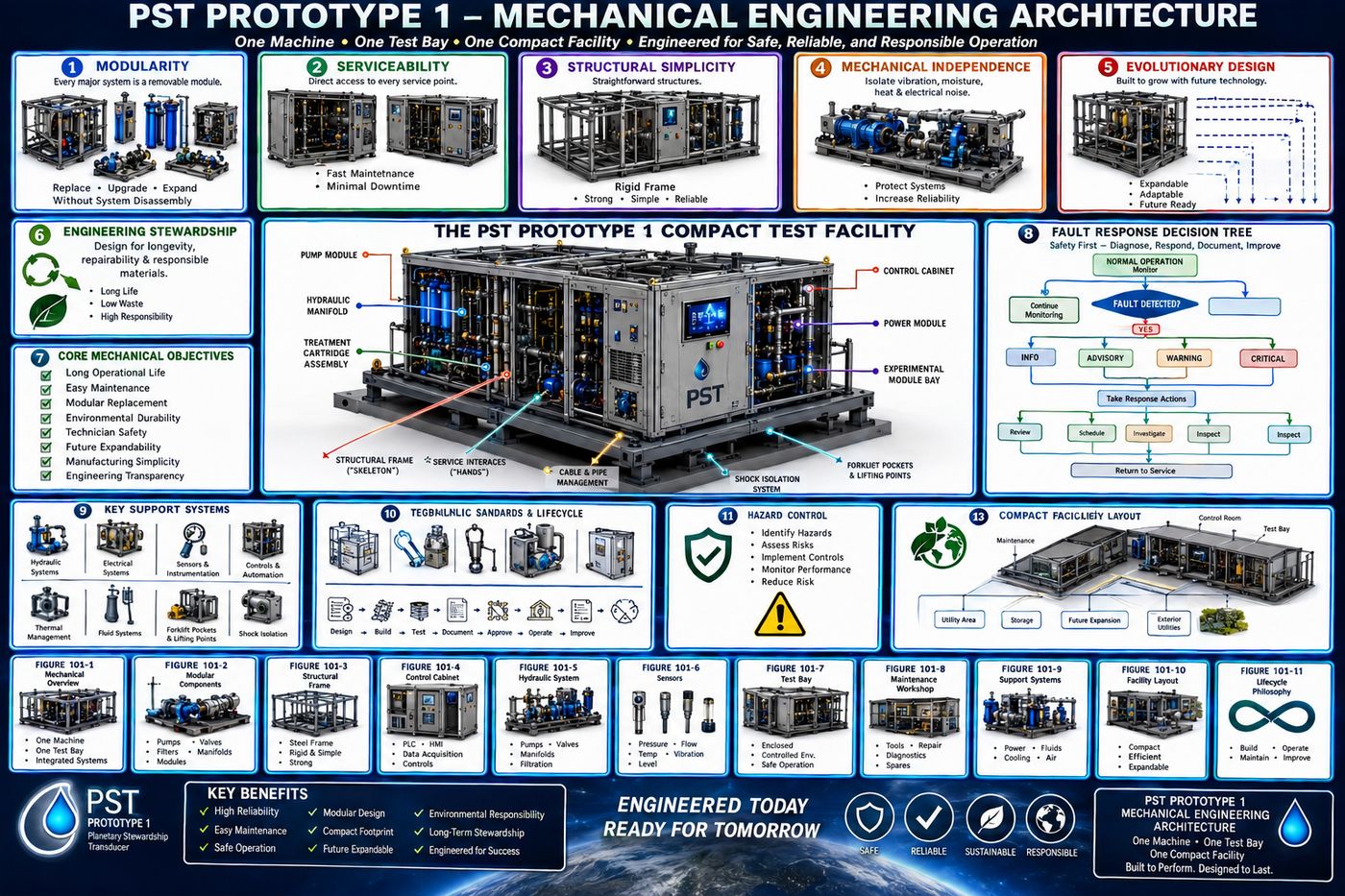
PST-101 defines the physical architecture of Prototype 1: the mechanical zones and functional organ hierarchy that organize the platform, the structural frame that carries every load, the modular enclosure that protects it, the standardized interface every replaceable module shares, and the detailed mechanical design of the platform's three primary organs, the Pump Module, the Treatment Cartridge Assembly, and the Experimental Module Bay, followed by the Cooling System, the service philosophy that governs maintenance over the platform's life, and the verification and acceptance process required before the platform enters service.
Eleven chapters are covered in full below, each following the specification's own structure: purpose, engineering objectives, design philosophy, subsystem architecture, and a chapter summary.
I. Overall Mechanical Architecture
Prototype 1 is approached not as a collection of individual components but as a complete engineering organism whose subsystems cooperate to perform a unified environmental mission. It is designed as a self-contained modular environmental engineering terminal, housed within a rigid structural frame supporting all mechanical, electrical, hydraulic, sensing, and control equipment, with every subsystem organized around the principle that no component should unnecessarily obstruct access to another.
1.1 The Eight Mechanical Zones
| Zone | Function |
|---|---|
| A — Structural Foundation | The mechanical backbone: carries structural loads, supports transportation, provides lifting points, anchors equipment, maintains dimensional stability. Never removed during normal servicing. |
| B — Utility Corridor | The primary routing pathway for electrical conduits, hydraulic lines, communications, drainage, cable management, and grounding conductors, kept separate to minimize interference between subsystems. |
| C — Treatment Bay | Houses the replaceable environmental processing modules, filtration, activated carbon, biochar, mineral media, biological treatment, and experimental cartridges, each independently replaceable with unobstructed service access. |
| D — Hydraulic Bay | Circulation pumps, manifolds, pressure regulation, bypass valves, sampling ports, and flow instrumentation, laid out to minimize pipe length while maintaining serviceability. |
| E — Power Bay | Battery systems, power conversion, distribution hardware, protection devices, and monitoring equipment, electrically isolated from wet-process equipment through physical separation and dedicated barriers. |
| F — Control Bay | The platform's central nervous system: controller, human-machine interface, data acquisition, communications hardware, and diagnostics, with environmental protection and thermal management prioritized. |
| G — Experimental Module Bay | Reserved for engineering research, experimental hydraulic devices, resonance chambers, quartz assemblies, advanced sensors, prototype hardware, intentionally isolated so research activity cannot compromise baseline performance. |
| H — Sensor Mast | Supports environmental instrumentation above the enclosure, meteorological instruments, atmospheric measurement, communications antennas, and positioning equipment, mechanically isolated to reduce vibration-induced measurement error. |
1.2 Layout Philosophy
Four organizing rules govern the overall layout. Heavy components stay low, for a lower center of gravity, improved transport stability, reduced structural loading, and increased wind resistance. Wet systems stay separate from dry systems wherever practical, minimizing the consequences of leaks and simplifying inspection. Service paths stay straight, so technicians can remove major assemblies without dismantling unrelated systems, and accessibility is progressive: components requiring frequent inspection sit nearest the service doors, while components requiring infrequent replacement may occupy deeper positions.
Mechanical stability is further supported by concentrating mass toward the platform's geometric center, targeting symmetrical loading, minimized overturning moment, balanced transport loading, and predictable lifting behavior, with center-of-gravity location to be verified through engineering analysis and prototype testing. The overall footprint is intended to remain compatible with standard transportation equipment, forklift handling, crane lifting, trailer transport, and modular installation, with dimensional optimization balancing portability against adequate internal service volume, and a defined service envelope providing clearance for door opening, cartridge replacement, pump removal, electrical inspection, and sensor calibration as part of the operational footprint.
II. The Mechanical Organ Hierarchy
For clarity and systems engineering, the platform is described using a functional hierarchy of ten cooperating "organs," an engineering analogy intended to communicate how independent subsystems interact to support the operation of the whole.
| Organ | Primary Assembly | Core Responsibility |
|---|---|---|
| Skeleton | Structural Frame | Carries structural loads and maintains dimensional accuracy; remains permanently installed |
| Skin | External Enclosure | Environmental protection, weather sealing, physical security, and service access |
| Heart | Hydraulic Pump Module | Circulates process fluids and generates the pressure that supports every treatment operation |
| Circulatory System | Piping and Manifolds | Transports and directs fluid between treatment stages, supports bypass and maintenance flushing |
| Digestive System | Treatment Cartridge Assembly | Filtration, adsorption, mineral conditioning, biological and experimental processing |
| Brain | Control Cabinet | Coordinates operation, executes control logic, manages alarms, supervises automation |
| Nervous System | Sensor Network | Observes conditions, monitors internal operation, and supplies the data the Brain acts on |
| Lungs | Cooling System | Removes heat and regulates enclosure temperature to protect electronics and measurement accuracy |
| Immune System | Diagnostics Module | Detects faults, monitors subsystem health, and supports predictive maintenance |
| Hands | Service Interfaces | Human interaction, maintenance access, module replacement, calibration, and commissioning |
The organs operate through continuous interaction rather than isolation: the Brain receives information from the Nervous System and directs the Heart, the Heart supplies the Circulatory System, the Circulatory System delivers fluids to the Digestive System, the Lungs regulate temperature for the Brain and Power systems, the Immune System monitors every organ simultaneously, and the Hands let technicians inspect, service, and replace individual organs without disrupting the platform as a whole. Each organ is designed for independent replacement wherever practical, reducing downtime and lifecycle cost, and the hierarchy is intentionally expandable: future prototype generations may introduce additional organs, such as an energy storage organ or a distributed network organ, without altering the existing structure. The terminology also serves human factors, giving technicians a consistent language for identifying which organ performs a function, requires maintenance, reported a fault, or is being upgraded.
III. Structural Frame Engineering
The structural frame is the primary load-bearing assembly and the permanent mechanical backbone of the platform: unlike replaceable operational modules, it is intended to remain in service throughout the platform's entire lifecycle while accommodating future subsystem upgrades. Its engineering objectives include maintaining geometric stability under operational loading, supporting transportation and installation without permanent deformation, providing standardized mounting interfaces for every major subsystem, minimizing vibration transmission, maintaining alignment across the platform's operational life, and supporting future expansion without requiring redesign of the primary structure.
Prototype 1 adopts a space-frame architecture of standardized structural members arranged to maximize stiffness while minimizing material, emphasizing simplicity, repeatability, manufacturability, inspection access, and repairability; complex geometry is introduced only where structural analysis demonstrates a clear benefit.
3.1 Six Structural Regions
| Region | Function |
|---|---|
| A — Base Chassis | Supports the full system weight, distributes loads to the installation surface, provides forklift access and lifting provisions, anchors all upper members, and resists torsional deformation during transport |
| B — Vertical Columns | Transfer loads between the upper frame and base chassis, maintain enclosure alignment, support service doors, carry roof loads, and resist lateral wind and transportation loading |
| C — Upper Structural Ring | Ties the vertical members together for roof support, sensor mast mounting, cable support, and overall frame rigidity, and serves as a mounting platform for future expansion |
| D — Internal Equipment Rails | Dedicated structural rails carry internal equipment loads rather than the enclosure panels, simplifying assembly, module replacement, and load distribution |
| E — Cross Bracing | Resists racking, transportation vibration, wind loading, asymmetric lifting, and seismic disturbance where applicable, positioned to maximize stiffness without obstructing service paths |
| F — Roof Structure | Supports environmental protection, optional solar modules, the sensor mast, communications hardware, and maintenance lifting, kept structurally independent from removable service panels where practical |
Every major subsystem mounts to standardized structural interfaces, slotted rails, precision locating holes, captive fastener provisions, isolation mounts, alignment pins, and modular support brackets, so subsystems can evolve independently while remaining compatible with the primary frame. Loads are grouped into static (equipment, battery, and fluid mass, structural self-weight), dynamic (pump vibration, transportation acceleration, maintenance activity, wind-induced vibration), and environmental (snow, rainwater, thermal expansion, seismic loading where applicable) categories, with the frame designed to transmit these efficiently to the foundation while minimizing localized stress concentration.
Vibration management favors controlled damping over absolute rigidity, through balanced equipment placement, isolation mounts, flexible couplings, and frame stiffness tuned to avoid resonance. Long-term outdoor operation is supported through protective coatings, corrosion-resistant hardware, drainage paths, cavity ventilation, and isolation of dissimilar metals, with inspection access to periodically evaluate protective systems. Transportation is supported through integrated forklift pockets, certified lifting eyes, tie-down locations, center-of-gravity markings, and transport locking for removable modules, without requiring removal of permanent structural members, and the platform is designed to interface consistently with multiple foundation types, reinforced concrete pads, steel skid frames, temporary field platforms, and modular utility pads. The frame carries intentional reserve capacity for future additions, additional treatment modules, expanded batteries, larger sensor arrays, enhanced communications, and future experimental modules, added through predefined mounting locations rather than structural modification. Before deployment, the frame undergoes dimensional inspection, weld inspection, fastener verification, surface coating evaluation, static load assessment, transportation simulation, and alignment confirmation, with deviations documented through the PST-002 configuration management process.
IV. Modular Enclosure Engineering
The enclosure protects the platform's internal systems while providing organized, efficient access for operation and maintenance. It is not part of the primary load-bearing structure; instead it functions as a removable protective shell supported by the structural frame, prioritizing environmental protection, technician accessibility, modular replacement, and long-term durability. Rather than a single welded shell, Prototype 1 divides the enclosure into independently removable service panels, enabling individual panel replacement, reduced repair cost, easier shipping, simplified upgrades, and better inspection access, with no single panel intended to prevent access to unrelated systems.
4.1 Panel Groups
| Panel Group | Provides Access To |
|---|---|
| Front Service Doors | The primary operator interface: HMI, status indicators, emergency stop, main disconnect, and routine inspection ports, without exposing internal mechanical systems |
| Hydraulic Service Panels | Pumps, valves, manifolds, flow meters, sampling ports, and drain connections, serviceable independently of electrical work |
| Treatment Bay Doors | Cartridge replacement, filter inspection, media removal, sampling chambers, and flush connections, fully serviceable without disturbing adjacent modules |
| Electrical Access Panels | Power distribution, battery systems, circuit protection, power monitoring, and wiring inspection, isolated from fluid systems |
| Rear Service Doors | Communications hardware, cable routing, internal utilities, and structural inspection, simplifying installation and future upgrades |
| Roof Access Panel | The sensor mast, communications antennas, solar wiring, and environmental instruments, serviceable without entering process compartments |
The enclosure is designed against rainfall, wind-blown dust, snow accumulation, UV exposure, temperature cycling, splashing water, and small wildlife, balancing environmental sealing with adequate ventilation, filtered intake and protected exhaust vents, directed airflow, separate cooling zones, and serviceable filters, while managing condensation and drainage through sloped panel geometry, internal drainage channels, weep holes, drip shields, cable drip loops, and elevated electronics mounting so standing water never accumulates in enclosed spaces. The service philosophy is strict compartmentalization: replacing a filter cartridge should never require opening electrical panels, inspecting batteries should never expose treatment media, and servicing communications hardware should never disturb hydraulic piping. Fastening is standardized wherever practical, common sizes, captive hardware, tool compatibility, and corrosion-resistant materials, and every panel carries durable identification of its designation, associated subsystem, access precautions, orientation, and revision. Noise transmission is reduced through isolated equipment mounting and acoustic insulation without compromising cooling or accessibility, and the architecture is designed to accommodate future revisions, larger cartridge bays, additional doors, expanded ventilation, and new experimental compartments, through panel replacement or extension rather than a full enclosure redesign.
V. The Mechanical Module Interface Standard
Every replaceable assembly, hydraulic modules, treatment cartridges, electrical equipment, communications hardware, sensors, and future experimental systems, interfaces with the platform through a common mechanical connection standard. Prototype 1 is built around interchangeable engineering modules rather than permanently integrated hardware: the frame remains constant, and the modules evolve. Every major module connects through a structural mounting surface, precision locating features, primary fastening points, alignment guides, vibration isolation where required, defined service clearance, and an identification plate, so future modules inherit the same mounting geometry regardless of internal function.
Longitudinal equipment rails mounted directly to the structural frame provide repeatable positioning, adjustable mounting locations, simplified installation, load distribution, and future expansion capability, with modules sliding into position before final fastening. Alignment is achieved through dedicated locating features, locating pins, precision shoulders, guide blocks, tapered alignment cones, and machined reference surfaces, rather than relying on fasteners, whose role is retention only, not alignment; separating the two makes assembly repeatable, reduces wear, and minimizes installation errors. Vibration-sensitive assemblies, circulation pumps, sensitive sensors, communications equipment, and electronic controllers, are isolated using elastomeric mounts, spring isolators, flexible couplings, or damping pads. Modules intended for routine replacement support front-access removal, minimal tool changes, unobstructed lifting, visible fasteners, standardized connectors, and guided insertion, each within a defined service envelope planned during initial design rather than retrofitted afterward. Every module carries permanent identification, designation, engineering revision, serial number, mass, installation orientation, service instructions, and manufacture date, and future equipment, upgraded pumps, improved treatment systems, expanded batteries, revised controllers, and experimental modules, is intended to remain mechanically compatible with the Prototype 1 architecture through module replacement rather than platform redesign. Before installation, each module interface is evaluated for dimensional accuracy, mounting alignment, fastener engagement, vibration isolation, accessibility, and service clearance.
VI. Pump Module Engineering — The Heart
The Pump Module is the primary mechanical driver of fluid circulation, providing controlled water movement through the treatment architecture while maintaining stable hydraulic conditions for measurement, experimentation, and long-term operation. It is designed as a completely removable assembly, allowing maintenance, replacement, or future upgrade without structural modification of the platform, emphasizing continuous operation, mechanical reliability, low vibration, ease of replacement, and standardized mounting; it is a replaceable organ, not a permanent structural component.
The module comprises a rigid pump base plate providing structural stiffness, alignment, and a mounting interface; a primary pump responsible for continuous circulation, controlled flow, stable pressure, continuous-duty operation, and serviceable mechanical seals, with specific pump selection dependent on the intended application; a flexible coupling separating motor vibration from pump loads while accommodating minor alignment variation; a drive motor mounted independently to minimize vibration transmission; an isolation mount assembly supporting the complete pump package on vibration-isolating mounts between the module base and structural frame; and a removable service tray sliding along the standardized rails, allowing complete removal without disturbing adjacent equipment.
Routine servicing requires only electrical isolation, hydraulic isolation, release of module fasteners, disconnection of quick-service interfaces, and removal along the service rails, with no structural disassembly required. Since the pump is one of the largest sources of mechanical vibration in the platform, elastomeric isolation mounts, flexible hydraulic connectors, balanced rotating assemblies, and frame design that avoids structural resonance work together to keep operation stable rather than eliminate vibration entirely. Routine maintenance items, coupling inspection, lubrication points, mounting hardware, isolation mounts, and electrical and hydraulic interfaces, remain directly accessible without removing unrelated modules. Future pump assemblies, higher-capacity units, redundant circulation, variable-speed configurations, specialized process pumps, and experimental hydraulic devices, are accommodated through the same standardized mounting architecture. Verification covers mounting alignment, vibration assessment, fastener inspection, coupling inspection, isolation mount compression, rotational clearance, and a service removal demonstration, and because the module is expected to undergo multiple replacement cycles over the platform's life, its design prioritizes repeatable installation, minimal downtime, standardized spare parts, and documented service procedures. Mechanically independent, the Pump Module still interfaces directly with the structural frame, hydraulic manifold, treatment cartridge assembly, electrical power system, control system, and sensor network, supporting nearly every functional subsystem in the platform.
VII. Treatment Cartridge Assembly Engineering — The Digestive System
Rather than relying on permanently installed treatment media, the platform uses interchangeable cartridge assemblies that can be installed, serviced, replaced, or upgraded without modifying the surrounding mechanical infrastructure, built around five guiding principles: modularity, accessibility, replaceability, expandability, and mechanical repeatability. Treatment media are expected to evolve over the platform's life; the supporting mechanical architecture is designed to remain constant while cartridge contents change as engineering knowledge advances.
Each treatment bay consists of a structural support frame, cartridge guide rails, a locking mechanism, inlet and outlet manifolds, sampling interfaces, drain connections, and identification plates, forming a self-contained treatment compartment. Every cartridge follows a standardized format, mechanical housing, top and bottom service connections, alignment guides, an identification label, a service handle, a drain interface, and an inspection window where practical, so multiple treatment technologies can share the same mechanical interface. Representative cartridge categories include filtration cartridges for suspended solids, carbon or biochar cartridges for adsorptive conditioning, mineral conditioning cartridges, biological cartridges for controlled biological media, and experimental cartridges reserved for future investigation, all mechanically compatible with the standard architecture regardless of internal design.
Cartridges are supported independently through dedicated mounting brackets attached directly to the structural frame, so enclosure panels provide protection but never carry cartridge loads, and guided insertion provides automatic alignment so a technician never needs to manually align fluid connections during installation. Each cartridge includes a positive mechanical locking system for secure retention, vibration resistance, tool-assisted release, and visual confirmation of engagement. Routine replacement follows eight steps: isolate hydraulic flow, depressurize the cartridge, drain residual fluid, release the locking mechanism, withdraw the cartridge along its guide rails, install the replacement, restore flow, and verify operation, without disassembling adjacent modules. Sampling ports are positioned for upstream and downstream measurement, cartridge performance comparison, and maintenance verification, remaining accessible with cartridges installed. Since treatment cartridges are expected to experience the highest replacement frequency of any major subsystem, the surrounding architecture emphasizes rapid service, repeatable alignment, standardized interfaces, technician safety, and minimal downtime, verified through alignment inspection, insertion force evaluation, locking confirmation, leak inspection, drainage verification, and replacement repeatability testing.
VIII. Experimental Module Bay Engineering
The Experimental Module Bay is a dedicated engineering compartment for integrating, evaluating, and validating future technologies without compromising the integrity of the baseline platform. Prototype 1 deliberately separates validated operational systems from experimental investigation, protecting baseline operation, improving engineering traceability, reducing experimental risk, and supporting repeatable testing; experimental hardware should never require structural modification of the platform. The bay itself is not a device but a standardized research compartment: the compartment remains constant while the experimental hardware installed within it changes.
Its architecture includes a dedicated structural mounting frame, the standard mechanical interface, adjustable equipment rails, a utility access corridor, environmental isolation barriers, instrumentation mounting locations, an observation access panel, and a defined service clearance envelope, with standardized access to common platform utilities, electrical power connection points, sensor communication interfaces, data acquisition access, and hydraulic service connections where applicable, without the compartment prescribing the experimental device itself. Experimental equipment is mechanically isolated from validated operational systems wherever practical, to prevent unintended interference, protect baseline measurements, and simplify troubleshooting, functioning as an independent engineering test environment supported by configurable mounting rails, transverse slots, adjustable brackets, standardized bolt patterns, and removable equipment shelves for hardware of varying size and geometry.
Observation during testing is supported through inspection windows, internal lighting, camera mounting provisions, sensor attachment points, and instrument access ports, ideally without disturbing the experimental configuration. Experimental hardware is removable as a complete assembly through a seven-step sequence: disable utilities, disconnect standardized interfaces, release mounting hardware, withdraw the module, install the replacement, verify interfaces, and resume testing. Each installation receives a module designation, revision identifier, installation date, test campaign identifier, engineering owner, and configuration record, so experimental results remain traceable and reproducible. The compartment is intentionally technology-neutral, with potential future applications including novel treatment media, advanced sensing concepts, alternative hydraulic devices, and mechanical design evaluations, and is expected to experience the highest rate of configuration change in the platform, so its design emphasizes modularity, flexibility, documentation, and rapid reconfiguration over fixed structure.
IX. Cooling System Engineering — The Lungs
The Cooling System maintains acceptable operating temperatures by regulating heat generated by electrical, mechanical, and computational subsystems, preserving equipment reliability, sensor accuracy, component life, and stable operation across a wide range of environmental conditions. It is designed as a passive-first, active-assisted architecture emphasizing simplicity, serviceability, and energy efficiency, managing heat in stages rather than through a single mechanism: passive dissipation first, then natural convection, then directed airflow, then active ventilation, then supplemental thermal management only where required.
9.1 Five Thermal Zones
| Zone | Contains | Thermal Consideration |
|---|---|---|
| A — Power Compartment | Batteries, power electronics, distribution hardware | Typically the highest continuous thermal load; receives dedicated airflow |
| B — Control Compartment | Controller, HMI, communications, data storage | Stable temperature is particularly important for long-term electronic reliability |
| C — Hydraulic Compartment | Pumps, valves, manifolds | Largely mechanical heat, isolated from the control compartment |
| D — Treatment Bay | Treatment cartridges | Generally follows ambient conditions; cooling is secondary to stable treatment operation |
| E — Experimental Module Bay | Variable, depends on installed research module | Supports configurable airflow and optional auxiliary cooling without affecting adjacent systems |
Air moves through the enclosure in a controlled, predictable manner: filtered intake at lower elevations, directed upward movement through equipment, separate pathways for power and electronics, and exhaust at upper elevations, preventing hot-air recirculation. Intake air passes through serviceable filters reducing dust, insects, plant material, and airborne debris, replaceable without opening major equipment compartments. High-temperature components are physically separated from temperature-sensitive instrumentation, power conversion from sensor electronics, pump motors from control systems, experimental heat sources from baseline measurements, reducing measurement drift. Routine maintenance, filter inspection, fan inspection, airflow verification, vent cleaning, drain inspection, and thermal sensor verification, occurs through dedicated access panels without disturbing unrelated equipment, and the architecture accommodates future higher-capacity electronics, expanded batteries, and larger experimental modules through modular expansion rather than complete redesign. Since outdoor equipment experiences temperature cycling that can produce internal condensation, the enclosure incorporates controlled ventilation, drainage pathways, elevated electronics mounting, moisture-resistant cable entries, and weather-protected vents, so condensation never accumulates around critical electrical assemblies. Although the Cooling System performs no environmental treatment directly, it directly influences power system reliability, control system stability, sensor accuracy, communications performance, experimental repeatability, and overall platform longevity.
X. Mechanical Service Philosophy
The Mechanical Service Philosophy establishes the principles governing inspection, maintenance, repair, replacement, and long-term stewardship of Prototype 1, organizing maintenance into four progressive service levels.
| Level | Representative Activities |
|---|---|
| 1 — Routine Inspection | Visual inspection, indicator review, filter inspection, leak observation, vent cleaning, external cleaning; no component removal normally required |
| 2 — Preventive Maintenance | Cartridge and filter replacement, fan inspection, sensor calibration, lubrication where applicable, fastener verification, on scheduled intervals |
| 3 — Module Replacement | Removal of complete assemblies: pump module, power module, control cabinet, experimental module, communications assembly, via standardized interfaces |
| 4 — Structural Service | Infrequent: structural inspection, frame repair, surface refinishing, corrosion treatment, foundation inspection, major refurbishment |
Every maintenance activity begins with accessibility: direct service paths, clear hand access, minimal obstruction, and logical component arrangement, so no frequently serviced component requires unnecessary removal of unrelated equipment. Routine maintenance relies on a minimal set of commonly available tools, standard fastener sizes, common wrench dimensions, modular lifting fixtures, and portable diagnostics, reducing tool diversity to simplify field service and training. Every activity is documented, date, technician, module identification, observations, replaced components, calibration results, and verification status, supporting engineering traceability and long-term reliability analysis. Human factors, comfortable working heights, adequate lighting, clear labeling, accessible lifting points, and logical service orientation, reduce maintenance errors and improve safety, and where practical the platform supports predictive maintenance based on equipment condition, vibration trends, temperature trends, pressure changes, flow deviations, power consumption, and diagnostic alerts, rather than fixed schedules alone.
Prototype 1 encourages replacing complete modules in the field, with removed modules refurbished, upgraded, tested, and re-certified at the workshop, minimizing downtime while improving repair quality. Every mechanical subsystem is evaluated across its complete lifecycle, expected service life, inspection interval, replacement interval, refurbishment potential, and recyclability, and following any maintenance, verification confirms proper installation, mechanical alignment, fastener integrity, leak-free operation, sensor functionality, and safe restart before the work is considered complete. This service philosophy is intended to remain consistent throughout future PST generations regardless of how much larger or more capable those platforms become.
XI. Mechanical Verification and Acceptance Testing
This program establishes the procedures confirming that Prototype 1 has been assembled correctly, operates safely, and satisfies its mechanical design requirements before entering service. Verification is not intended to demonstrate environmental performance or validate research hypotheses; its purpose is to confirm the mechanical platform was built to specification and is ready to support operational testing. Prototype 1 is accepted through objective verification rather than assumption, emphasizing safety, repeatability, documentation, traceability, configuration control, and engineering accountability.
11.1 Seven Verification Categories
| Category | Confirms |
|---|---|
| A — Structural Integrity | Frame geometry, weld inspection, structural alignment, anchor interfaces, mounting rail alignment, surface protection |
| B — Mechanical Assembly | Fastener installation and torque, module alignment, panel fit, door operation, mechanical clearances |
| C — Motion Verification | Freedom of movement, alignment, interference, and travel limits for every moving assembly, with no unintended contact across the full range of motion |
| D — Service Verification | Demonstrated cartridge replacement, pump module removal, panel removal, filter replacement, experimental module exchange, and sensor access, without unnecessary disassembly |
| E — Environmental Protection | Door and panel sealing, drainage pathways, vent protection, corrosion protection, weather barriers |
| F — Transportation Readiness | Forklift access, lifting points, tie-down provisions, module retention, center-of-gravity identification |
| G — Configuration Verification | Correct revision levels, module identification, installed options, configuration and maintenance baseline records |
11.2 The Seven-Step Acceptance Sequence
Acceptance follows a structured sequence: documentation review, confirming current engineering drawings and configuration records; visual inspection of overall workmanship and component installation; structural verification of frame integrity and mounting accuracy; mechanical function testing of service doors, removable assemblies, guide rails, locking systems, and access panels; a service demonstration performing representative maintenance activities; safety verification of guards, access controls, lifting provisions, and operator safety features; and finally acceptance documentation, recording inspection results, deviations, corrective actions, and final approval. Any observed deviation is classified as an observation, minor deviation, major deviation, or critical deviation, with corrective actions completed and verified before final mechanical acceptance, and every acceptance event produces a permanent engineering record that becomes part of the platform's history.
Verification is not limited to initial construction: major repairs, module replacement, structural modification, long-term storage, transportation damage assessment, and significant upgrades all trigger re-verification, maintaining confidence throughout the platform's lifecycle. Successful mechanical acceptance authorizes progression to the subsequent engineering disciplines, electrical, hydraulic, control, and sensor integration systems, manufacturing, installation, and commissioning, establishing the physical foundation those disciplines build on. The specification frames verification itself as an act of engineering stewardship: demonstrating that the platform has been assembled responsibly, documented accurately, and prepared for reliable long-term service, with the objective not simply to complete construction but to establish confidence in the engineering process itself.
Protected — Detailed Engineering Package
Detailed calculations, dimensional tolerances, material specifications, fastener and torque schedules, engineering drawings, the bill of materials, and fabrication packages for every assembly described above are held under NDA pending requirements freeze and physics validation, consistent with the source specification's own stated pre-construction status.
Full Specification Available Under Signed NDA ↗Documentation Summary
The mechanical zone architecture, the ten-organ functional hierarchy, the structural frame's six-region architecture, the modular enclosure's panel system, the Standard Mechanical Module Interface, and the detailed engineering of the Pump Module, Treatment Cartridge Assembly, Experimental Module Bay, and Cooling System are original work product of Joshua Farrior, developed under CHRISTOS™ Energy, Technology & Harmonic Design Consulting, LLC.
Held under NDA pending further development: dimensional tolerances and material specifications for every structural region and module; fastener, torque, and alignment specifications; the complete engineering drawing package; the bill of materials; and fabrication and acceptance test procedures beyond the verification categories described above.
© 2026 Joshua Farrior · Christos™ Energy, Technology & Harmonic Design Consulting, LLC · All Rights Reserved · Business ID: 202511071941923 · Christos™ trademark registered on the USPTO Principal Register · christosenergy.com